GSD 511
Objective : To verify the Truth Tables of Basic Logic Gate, Combinational Logic Circuits & Sequential Logic Circuits, Flip Flops,Shift Registers, Multiplexer, De- Multiplexer & Counter Circuits
Technical Specifications :
Output voltage (Regulated) :5V DC
Logic Inputs: 10 No’s. logic '0' & logic '1' ( Through Switches )
Output indicators : 10 No’s.
Clock : 1Hz Monoshot
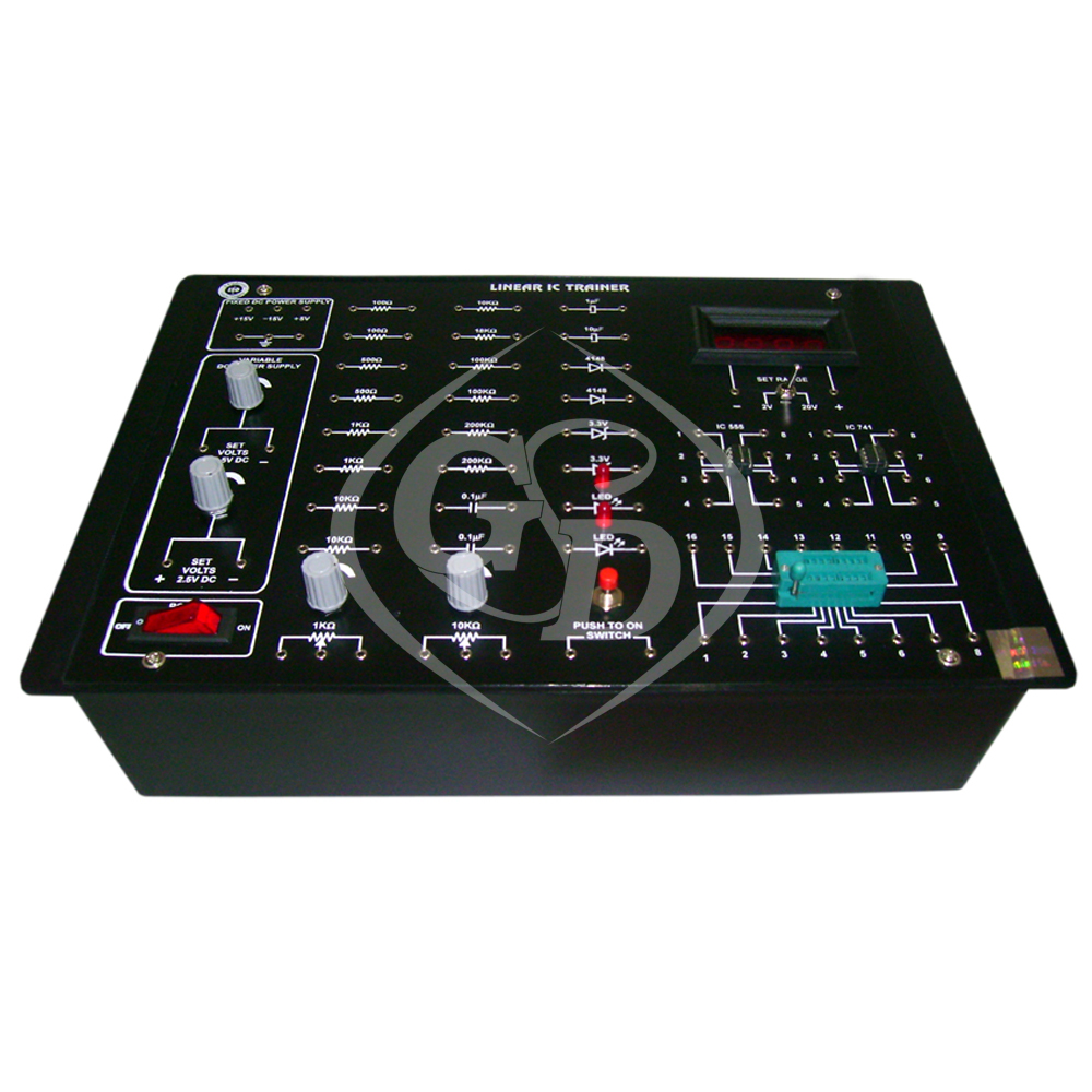
Housed in ABS cabinet , symbol diagram printed, connections of
various IC’s/ components ( NAND Gates, NOR Gates (4No’s each),
AND Gates , NOT Gates (2 No’s each), RS&D Type Flip Flop, Shift
Register, Multiplexer, De- Multiplexer & Counter).
All important outputs & test points brought out at Glass epoxy (PCB)
front panel. Also provided with patch chords & instruction manual.
Instruction Manual
2021 Gurunanak . All Rights Reserved